The File conversion rule editor help topic is used to help you with the Add/Edit Batch File Conversion Rule dialog box that is used to Add new file conversion rules and, to Edit the existing ones.
| Name | Defines the name of the conversion profile. |
| File type | Determines the output file format the selected documents are converted into with the selected file conversion rule. See the following Output File Types table for the further information about the supported output file types and their supported source document types. |
| Conversion Options | Additional conversion options. |
| Apply conversion rule to |
Sets the document type which the conversion rule applies to. Source document types that are not supported by the selected output file format, cannot be selected.
|
|
TIP: Click > to select the boolean from the menu. |
| Target filename (including the path) |
Defines the output filename and destination folder. If the destination does not exist, it will be created during the conversion process.
Click > to select pre-defined options for the output filename and its destination path. The following options are available:
Illegal characters in target path including the CustomProperty values included in it are automatically replaced by the underscores (_) during the file conversion process to avoid unexpected issues on the file conversion process. |
|
NOTE: The following filename options are available only if the output file type is Dxf (*.dxf) or Dwg (*.dwg):
|
File conversion rule could have a dynamic output path and the filename. CustomProperties that belong to the different property scopes, are color coded in the Target filename box so that you can recognize the parts of the target path and filename easier. The following colors are used to identify the blobs:
| Model property | |
| Cut-List property | |
| Drawing property | |
| Pre-defined function | |
| Invalid item |
If you get the invalid item blob into the target filename, please ensure that the item selected in the target filename exist and also check the spelling of the target filename item names.
Let's say you have a SOLIDWORKS part called 000001 Base Plate.sldprt located in D:\SOLIDWORKS Workspace\Steel Design\. Then, you have a file conversion rule for converting
documents to PDF format and, which destination file is set as {DRW_PATH}{DRW_FILENAME} in the Target filename box.
Using the PDF file conversion rule defined as described above, the conversion output file with the path created from the 000001 Base Plate.sldprt is
D:\SOLIDWORKS Workspace\Steel Design\000001 Base Plate.pdf.
Let’s say we have a sheet metal box assembly like shown in the following picture that have four (4) pieces of the same, configured sheet metal plate used as side walls of a sheet metal box. Two of the sheet metal plates are bended from the both ends and two of the plates are not bended anyhow.
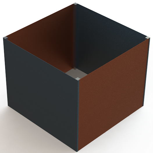
Picture 1. The Sheet Metal Box assembly referred in this example.
In this case, you may want to convert the DXF files from the sheet metal parts so that the output file names contain the part’s instance number and total quantity of the parts
in the whole assembly like follows.
<Path>\DXF\<PartNumber> <Configuration> <Instance no> of <Quantity>.dxf
To include the instance number and part’s total quantity in the output filename, include the following attributes in the Target filename of the file conversion rule used to convert the files into DXF.
So, the Target filename format in this example is {DRW_PATH}\DXF\{DRW_FILENAME} {SRC_CONF} {Instance number} of {Quantity}.
Full path including the filename of an assembly referred in this example is D:\Workspace\SOLIDWORKS Design\Sheet Metal Boxes\000003 Default.sldasm. Using the output filename
mentioned above in the File Conversion Rule, the output files' paths including the filename will be as follow:
You can also use the Windows environment variables to define the target path of the file conversion. The percent signs (%) in the both ends of the folder name means that the folder has been defined
as the local environment variable.
For Example: %TEMP%\%USERNAME%-DRW_FILENAME saves the output files into the temporary folder of the user which is currently logged into the Windows.
Complicated output path definitions could be implemented with help of the CustomTools Add-in scripts. If you need a script to define some more specific or otherwise complicated rules for the file conversion output folders, please contact CustomTools support by an email and specify your advanced conversion rule needs as accurate as possible.
| Specify location at runtime | The destination where the converted documents are saved is defined during the batch conversion processes. |
With CustomTools, you can convert your SOLIDWORKS documents to the following file formats.
| Supported Source Document Types | |||||
|---|---|---|---|---|---|
| File Type | File Extension | Parts | Assemblies | Drawings | |
| DWG | *.dwg | • | Additional Options | ||
| DXF | *.dxf | • | Additional Options | ||
| eDrawings Drawing | *.edrw | • | Additional Options | ||
| JPEG Image | *.jpeg | • | • | • | Additional Options |
| Adobe PDF | • | • | • | Additional Options | |
| TIFF Image | *.tif | • | • | • | Additional Options |
| VRML | *.wrl | • | • | • | Additional Options |
| ACIS | *.sat | • | • | • | Additional Options |
| ParaSolid | *.x_t | • | • | • | Additional Options |
| ParaSolid Binary | *.x_b | • | • | • | Additional Options |
| IGES | *.igs | • | • | • | Additional Options |
| STL | *.stl | • | • | • | Additional Options |
| STEP | *.step | • | • | • | Additional Options |
| Adobe PhotoShop | *.psd | • | • | • | Additional Options |
| IFC 2x3 | *.ifc | • | • | ||
| VDAFS | *.vda | • | • | ||
| Universal 3D | *.u3d | • | • | ||
| 3D XML | *.3dxml | • | • | ||
| Adobe Illustrator | *.ai | • | • | • | |
| Microsoft XAML | *.xaml | • | |||
| CATIA Graphics | *.cgr | • | • | • | |
| CATIA HCG | *.hcg | • | • | • | |
| HOOPS HSF | *.hsf | • | • | • | |
| eDrawings Part | *.eprt | • | Additional Options | ||
| eDrawings Assembly | *.easm | • | Additional Options | ||
Selected assembly or selected individual parts. Determines the configuration of the 3D model which are processed with the file conversion rule.
| Last active configuration | Process the configuration that was active last time the model was saved. |
| All configurations | Process all configurations of the selected model. |
| Embed in single file | Select this option to embed all configurations of the model to one output file.
NOTE: This option is available for the eDrawings part (.eprt) and assembly (.easm) file types only. |
| Named configuration | Process the configuration having the name specified in the Named configuration box. |
CustomTools file conversion rules could filter the model configurations to be processed. Filtering the configurations could be done by the sheet names using the boolean operators that are considered as the pre-defined functions. Pre-defined functions are color coded in the Named configuration box so that you can recognize the parts of the filter easier. The following colors are used to identify the blobs:
| Pre-defined function | |
| Invalid item |
If you get the invalid item blob into the format string of your sheet name filter, please ensure that the item selected in the sheet name filter exist and also check the spelling of the sheet name filter item names.
Sheets to convert. Determines how to choose the drawing sheets to be processed on the batch operation with this file conversion rule.
To process all sheets from all the drawings in the list, type an astersik (*) into the Sheets which name contains box or, leave the Sheets which name contains box empty.
| Sheets which name contains |
Defines the conditions used to determine how to choose the drawing sheets on batch operation with this file conversion rule. You can add more advanced rules to choose the desired sheets
by using the following boolean operators:
|
| ...and is referenced by model configuration |
Additional option related to the Sheets which name contains box to make the sheets to be selected also by the referenced model configuration.
For example if you have Sales* typed in the Sheets which name contains box and you have the and is referenced by model configuration option selected, the drawing sheets are selected if the sheet name and, the referenced model configuration of the sheet matches to the conditions. |
| Select last active sheet if condition(s) not met | Use this option to ensure that the batch operation have at least one drawing sheet selected. When this option is selected, the last active drawing sheet is processed even if any sheet does not meet the conditions defined. |
| Embed all sheets in the same target file |
Create a single file with all the sheets used in the drawing.
NOTE: The Embed all sheets in the same target file option is available only for the PDF, eDrawings (*.edrw), dxf and dwg documents. |
|
NOTE: The Sheets which name contains option and the text box associated to it, are not enabled if the selected document type is part or assembly. |
CustomTools file conversion rules could filter the drawing sheets to process. Filtering the sheets to convert could be done by the sheet names using the boolean operators that are considered as the pre-defined functions. Pre-defined functions are color coded in the Sheets which name contains box so that you can recognize the parts of the filter easier. The following colors are used to identify the blobs:
| Pre-defined function | |
| Invalid item |
If you get the invalid item blob into the format string of your sheet name filter, please ensure that the item selected in the sheet name filter exist and also check the spelling of the sheet name filter item names.
| After file is saved in SOLIDWORKS | Enable/Disable the automatic file conversion on Save operation.
This option cannot be selected with the DXF and DWG file conversion rules which have the Generate file from assembly according to the sheet metal part thickness option selected in their additional conversion options. |
When you have the After file is saved in SOLIDWORKS option selected, the following special behaviors are applied:
| Open output directory after rule is completed | Select this options to open the output folder defined in the Target filename box with the Windows Explorer after the file conversion is finished.
When you simultaneously run several file conversions having this option selected, the output folder of each file conversion rule having this option selected appears after the successful batch operation. NOTE: In case where more than one file conversion rule have the same output path defined in the Target filename box, only one instance of the Windows Explorer with the same output path appears after the file conversion. |
The Overwriting an existing file options are used to determine what to do on file conversion operation if the file with the same name already exist in the target path.
| Always | Overwrites existing files without any prompt during the batch operation. |
| Never | The existing files are never overwritten during the batch operation. |
| Prompt | The user gets prompted to decide whether or not to overwrite the file that already exist. |
You can make the DXF and DWG flat pattern documents straight from the SOLIDWORKS parts without creating the SOLIDWORKS drawings first.
To do that, create a file conversion rule which output file type is DXF or DWG and which applies to the part documents (Parts).
|
TIP: Also the multibody parts are handled by the file conversion rules that output file format is DXF or DWG. |
The following examples shows how the boolean operators could be used to determine drawing sheets' selection rules based on the sheet names.
| Boolean (symbol) | Syntax | Keywords in Sheet Names | Name Rule in Printing Profile | Description | Sheet Names to be Selected (Examples) |
|---|---|---|---|---|---|
| AND (&) | <Keyword 1>&<Keyword 2>... |
Sheets which name contain the following words:
|
Layout&Sheet |
Keywords Layout and Sheet are looked for from names of the sheets included in drawings refereced by the models in a structure the PrintAndConvert is used to be
executed against.
Sheets that name have both of the keywords included in an order they are defined in the selection rule, are included in the batch print operation. |
|
| OR (|) | <Keyword 1>|<Keyword 2>... |
Sheets which name contain at least one of the following words:
|
Layout*|*Sheet* |
Keywords Layout and Sheet are looked for from the sheet names included in drawings referenced by the models in structure opened in the
CustomTools PrintAndConvert feature. In this example, we also have some wild characters included in the keywords. Wild characters are considered as any set of characters in the sheet name.
Sheets that name starts with a word Layout or if the sheet name contain a word Sheet in anywhere, are included in the batch print operation. |
|
| NOT (!) | !<Keyword 1>&!<Keyword 2>... |
Sheets which name does not contain the following words:
|
!*DXF*&!*DWG* |
Keywords DXF and DWG are looked for from the sheet names included in drawings referenced by the models in structure opened in the
CustomTools PrintAndConvert feature. If a drawing's sheet name contain a word looked for, it is excluded from the batch print operation.
All other sheets except the ones that name contain a word defined in the selection rule, are selected and processed by the batch print operation. |
All other sheets are selected but, the ones named similar like shown in the following list, are excluded:
|