Cutting Profile
See the guide video on YouTube: Create a drawing sheet ready for Dxf Dwg use
The ATR CustomTools Cutting Profile feature is used to generate a cutting sheet from the part referenced in the selected drawing view. If no view is selected when the ATR CustomTools Cutting Profile is executed, the Cutting Profile generates a cutting sheet that includes all individual parts in the drawing. Different files and different model configurations of the same file are the unique factors used by the Cutting Profile in that case.
The cutting sheets generated with the ATR CustomTools Cutting Profile feature can be used to cut the parts to their desired shape with a laser cutting device, for example.
The following drawing sheet features and operations apply to the sheets generated by the Cutting Profile feature:
- Sheet scale. ATR CustomTools Cutting Profile feature generates the cutting sheets always using the 1:1 scale.
- Display mode. The Display mode setting of the Cutting Profile output sheets is set as Hidden lines removed. For that reason, the bending lines and other invisible lines of the view(s) are hidden in the output sheet.
- Annotations. All annotations like dimensions and notes are removed from the output sheet.
- View Order. Views in the output sheet are ordered so that the views in the output sheet are not interleaved.
The flat view in a drawing's cutting sheet created by the Cutting Profile references the SMFlatPattern model configuration, which is created automatically in the referenced model if it does not already exist. For that reason, the referenced model should be saved before running the Cutting Profile command against the drawing.
Because of the creation of new configurations in the referenced models, the models processed by the Cutting Profile operation are opened during the process and become unsaved. The unsaved models are left open after the operation to indicate to the user that they need to save the unsaved changes. If the referenced models are already open during the Cutting Profile process, they are just left open to indicate the user to save the unsaved changes. In these cases, the unsaved changes are the new configurations created by ATR CustomTools.
The following pictures describe how the Cutting Profile works in practice:
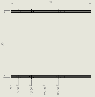
This picture represents a measuring sheet of the drawing created from a bended sheet metal plate which has holes on the bended sides.
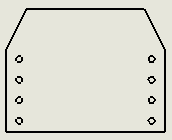
This picture is taken from DXF Sheet generated by the ATR CustomTools Cutting Profile feature.
When performing the Cutting Profile command on a drawing that already has a sheet created by the Cutting Profile, you are prompted whether you want to append or overwrite the existing sheet.
| Append | Appends the existing sheet by adding another instance of the part into the existing sheet created by the Cutting Profile. |
| Overwrite | Creates a new sheet to be used with the CNC machine by replacing the existing sheet created by the Cutting Profile. |
| Cancel | Cancels the Cutting Profile action. The DXF sheet is not created or the existing DXF sheet is not removed on the operation cancellation. |
Drawing sheets generated by the ATR CustomTools Cutting Profile feature are not intended to be modified by the user. The sheet that was active when the Cutting Profile operation was started is left as the active sheet once the Cutting Profile operation is finished.
Multibody parts are not supported by the ATR CustomTools Cutting Profile feature. To make the DXF files with the flatten views from your multibody parts, please use the ATR CustomTools Print/Convert feature in the File Conversion mode.
The Cutting Profile feature considers special holes in components, such as countersunk holes and holes that have other special features like a chamfer, a fillet, or a draft applied. The special features are handled so that only the cut-out of the hole itself is marked in the drawing sheet created. Outer bounds of the holes' special features (countersunk, chamfer, fillet, draft) are not included in a hole marking in the sheet created by the Cutting Profile feature.